3 Jul 2026 · updated 15 Sept 2026 · Ger
Build a bicycle wheel from start to finish
On this page
Give yourself a clear bench and several hours for your first wheel, especially if you are learning as you go. This guide puts the work in order and explains what to check at each stage. Use the calculator for spoke lengths and tension readings, and the stand and dish gauge to check the wheel itself. The lacing pattern must suit the chosen hub and rim.
Spoke tension is safety-critical. The rim maker’s published limit is the ceiling, and the hub and rim instructions outrank any general rule in this guide. If a limit or lacing restriction is missing, stop and ask the maker rather than borrowing a number from a similar component. If this is your first build, have an experienced builder inspect it before you ride it.
0 · Decide the build before buying spokes
Before calculating spoke length, check these parts:
- The hub and rim need the same hole count. Check axle, brake and freehub compatibility too.
- Choose the lacing pattern before calculating. The wheel-build advisor gives you a sensible starting point for hole count, crosses, spoke family and nipple material. The hub maker has the final word, especially for radial and straight-pull builds.
- Pick the actual nipples and any washers now. They change where the spoke seats, so they also change the ERD you need to measure.
This guide and the calculator inputs assume conventional wheels with equal spoke counts on each side. Patterns such as 2:1, G3 and paired holes need their own calculations and instructions; they fall outside this walkthrough.
1 · Put the right tools on the bench
Prepare the equipment for measuring, lacing and checking the wheel:
- Parts: hub, rim, the correct quantity and lengths of spokes, new nipples, and any washers the rim maker specifies.
- Measurement and prep: calipers, two reference spokes for ERD, a compatible thread treatment and nipple-seat lubricant, and something to keep left and right spoke lengths separate.
- Lacing and truing: a nipple driver or screwdriver, a spoke key that fits properly, a truing stand or the bike frame, and an independent alignment/dish gauge.
- Tension: a tensiometer with a conversion table for the exact spoke profile. Comparing pitch can help locate a spoke that differs from others on its side; use the meter and table for a tension estimate in kgf.
Use the lubricant, washers and spoke preparation specified for your components. Do not improvise around carbon rims or locking nipples: the nipple must turn smoothly without defeating the system the maker designed.
2 · Measure the hub and the real ERD
Treat database values as a starting point and check each record’s source, version and notes. There are manufacturer specifications and historical entries with varying levels of documentation. Check any uncertain dimension against your component before calculating.
For a J-bend hub you need the flange-hole circle diameter, centre-to-flange distance and spoke-hole diameter. Measure both sides independently. A straight-pull hub also needs the maker’s per-side spoke offset; do not substitute a J-bend flange measurement for it.
ERD is the number to distrust until you have measured it with the nipples and washers you will actually use. Repeat the measurement across a second pair of opposite holes. The complete method and convention are in how to measure ERD.
For an asymmetric rim, enter the offset magnitude without a minus sign and choose the side the holes sit towards. Left and right are viewed from the rider’s position. Your chosen direction stays the same when you change hubs. Check the Rim and Dish views against the actual orientation and the manufacturer’s instructions. In a saved file or the formula, the convention is fixed: positive to the right and negative to the left.
3 · Calculate and sanity-check both sides
Open the spoke-length calculator. Pick the hub and rim to fill the fields, or use manual entry for your measurements. Every database value remains editable, so replace the listed ERD with your measured one.

Enter the total spoke count and the pattern for each side. For straight-pull, switch the hub type and enter the published offset for each side. The result updates as you type.

Read the result in this order:
- Check the raw length on each side. A dished wheel normally produces two different raw values, though both can land on the same commercial size after rounding. On a symmetric rim-brake front, the two raw values should be equal.
- Choose the rounding rule deliberately. Down is the conservative default when a long spoke could bottom out. Nearest can give better thread engagement with compatible deep-thread nipples. Check the nipple maker’s drawing rather than using its overall length as a shortcut.
- Order by side. If the commercial sizes differ, order half the spokes in each length for a conventional wheel. If both sides round to the same size, order the full count in that size plus a couple of spares.
Cross-check a first build with a second calculator such as Freespoke, using exactly the same ERD convention and geometry. If the answers differ, work through ERD, the dimensions on each side, offset and rounding to find the cause. Resolve the difference before ordering spokes.
Name the calculation, press Save, then copy its link or export the JSON. This record contains the length inputs and rounding rule; the calculator recomputes the result when you load it. The tension readings will be saved separately later.
4 · Lace from one reference spoke
Sort and label the two spoke lengths before opening the packets. Inspect the rim holes, hub holes, spokes and nipples; stop if you find a crack, damaged thread or deformed seat.
Start with the key spoke beside the valve hole. Its position sets the valve window and the rest of the pattern. Complete one set of spokes, then the matching set, keeping the inside/outside orientation consistent. On a conventional crossed build, weave the final crossing only where the chosen pattern calls for it. A straight-pull hub already dictates the exit direction and pattern, so do not twist it into a different one.
For supported conventional J-bend patterns, use the Lacing view to check the key spoke, valve window and the two spoke groups. Check each spoke’s position before moving to the next group. For straight-pull, follow the manufacturer’s diagram: the calculator produces a length, but its viewer does not represent that hole layout.
Thread every nipple to the same visible depth. A nipple driver makes this faster, but stop before it bottoms out. At this point the wheel should be loose and even, with no spoke carrying meaningful tension on its own.
5 · Build tension while keeping the rim round and centred
The working loop is simple: round, true, dish, raise tension, then check all four again.
- Bring every nipple up in equal small turns around the whole wheel. Do not finish one sector while the rest is loose.
- Remove the largest radial errors while tension is still low. Spread a correction over several neighbouring spokes rather than making one large turn.
- Correct lateral wobble, then check the dish with an independent gauge. A wheel can look centred in a truing stand even when the stand is misadjusted.
- Raise the overall tension in another complete pass. Use quarter turns as the target approaches, then repeat the radial, lateral and dish checks.
The higher-tension reference side is normally the drive side on a rear wheel and the rotor side on a disc front. A symmetric rim-brake front has no lower-tension side. Do not choose a final target for the lower side independently: centre the rim, set the safe reference-side tension, and let the wheel geometry determine the other side.
Press Tension this wheel in the length calculator to open the tension tool. The handoff preloads the spoke count, reference side, a rounded geometry-based ratio and a provisional 110 kgf reference target. It also carries the name and wheel identity. Before measuring, adjust the working target according to your rim maker’s guidance.
If the maker publishes only a maximum tension, allow room for differences between spokes.
Choose a working target and tolerance that keep the complete band below it:
target × (1 + tolerance / 100) ≤ rim maximum. Ask the maker or an experienced builder if you do
not have enough information to choose that margin.
The tool has two tolerances: balance, around each side’s mean, and target, around the specified tension. Check both before measuring. The initial ±20% is broad; adjust it according to the component specifications and the wheel’s intended use.
Select the exact supported tensiometer and spoke model or profile. Do not use a nearby column just because the dimensions look similar, and never extrapolate beyond a conversion table’s range. Check your individual meter against its maker’s calibration or recalibration procedure before the final pass; a model-level table cannot correct a unit that has drifted. Measure every spoke with the same tool position and technique, one complete side at a time. Missing or invalid readings leave that side’s mean marked as provisional.
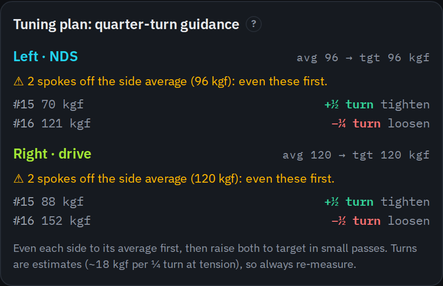
Balance compares each spoke with its own side’s mean; Target compares it with the working tension. The windows below the summary show kgf limits and equivalent readings. Check both criteria and each individual spoke, alongside trueness and dish.
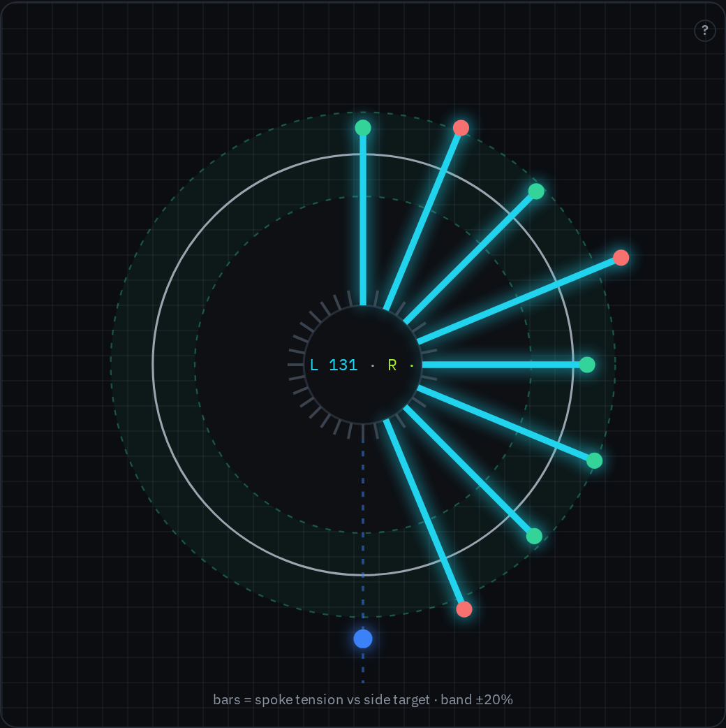
With supported built-in profiles, the plan prioritises evening each side around its mean, then approaching the target band. Its turns are estimates: try a small correction, complete another measurement pass and check true and dish before continuing.
Import a table for another instrument or spoke through My tension tables. Check its source, units and calibration. These tables operate in diagnostic mode, with conversions and working windows; turn advice and simulator loading are disabled.
6 · Remove wind-up, stress-relieve and repeat
Settle the wheel in a controlled way using a stress-relieving method suitable for its components. Mark round spokes with small tape flags or hold bladed spokes straight so you can see wind-up. Squeeze suitable spoke pairs by hand and seat J-bend heads and elbows using a method approved for the components. Do not blindly lever a carbon rim against the floor or copy a forceful method intended for another wheel.
After each stress cycle, check radial and lateral true, dish, reference-side tension and the spread within both sides. Correct in small passes. The wheel is ready when another controlled stress cycle no longer changes those measurements in a meaningful way.
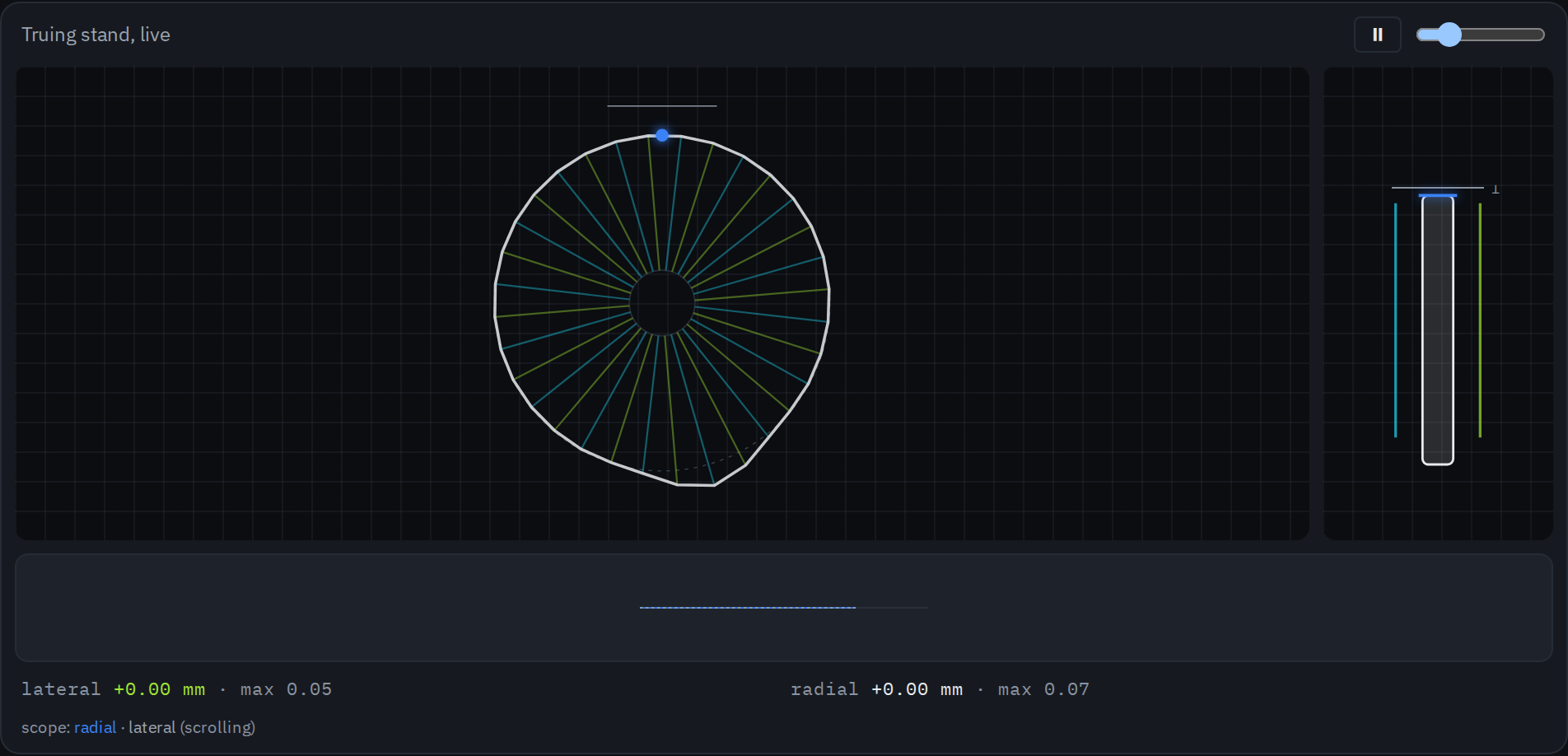
The truing simulator is useful before you touch the real wheel. It shows the direction and neighbourhood of a correction, but its quarter-turn response is qualitative. Use readings and gauges to decide the adjustments on your wheel; the simulator does not specify a tightening torque for those components.
7 · Run the final checks
Before fitting rim tape and tyre, check the bare wheel:
- Every spoke reaches the nipple’s intended thread engagement without bottoming out, and every bladed spoke is straight.
- The rim is radially round and laterally true, and a dish gauge confirms that it is centred over the hub.
- The reference side stays below the rim maker’s maximum, and spokes on the same side form a tight, explainable spread rather than a few high and low outliers cancelling each other.
- Nipples and washers sit correctly, the valve window is clear, and no rim or hub hole shows damage.
Fit the tape and tyre only after the bare-wheel checks pass. Inflation can reduce spoke tension, so recheck true and dish at riding pressure and record the change if it is useful for future service. A large or uneven change needs investigation, not another guessed turn.
8 · Save the two records
Length and tension are currently two separate local records:
- Save or export the length build for hub geometry, ERD, pattern and rounding. The lengths are recalculated when you load it.
- Save or export the tension build for the device, spoke profile, targets and readings. If you used a custom table, its exact revision is included.
Each tool creates its own share link and JSON file. Keep both with the spoke order or workshop notes to recover the dimensions and readings. Saves are local to the browser; export the files or copy their links to carry on elsewhere.
If a database value is wrong or a step here is unclear, open a GitHub issue. A specific correction with a maker source is the most useful contribution you can make.